
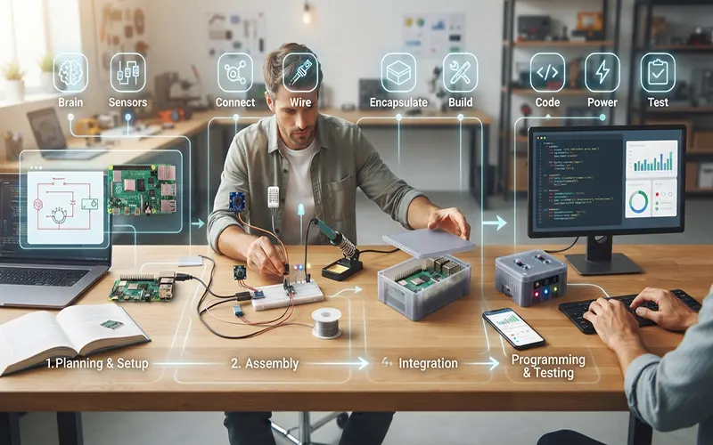
Off-the-shelf smart home gadgets are convenient, but they are often restricted by closed ecosystems, proprietary apps, and rigid feature sets. For developers and makers who want total control over their hardware, building a custom connected device is the ultimate solution.
The Raspberry Pi ecosystem empowers engineers to prototype industrial-grade smart objects quickly and affordably. By combining low-cost sensors, Python programming, and lightweight messaging protocols, you can transform a single-board computer into a fully functional, cloud-connected IoT monitoring node.
Hardware Bill of Materials and Architecture
Before writing a single line of code, you need to assemble the physical building blocks of your IoT node:
- Core Processor: The Raspberry Pi Zero 2 W or Raspberry Pi 4/5 serves as the brain of the project, providing built-in Wi-Fi and Bluetooth connectivity for remote data transmission.
- Sensors and Actuators: For this build, we will use a DHT22 temperature and humidity sensor, an RGB status LED to indicate connection states, and a push button for manual triggers.
- Wiring and GPIO Overview: You will need a half-size breadboard, male-to-female jumper wires, and a
pull-up resistor for the sensor data line. Safety first: always double-check voltage levels (
logic) to avoid damaging your Pi’s General Purpose Input/Output (GPIO) pins.
Step 1: Hardware Assembly and Circuit Wiring
Connecting physical peripherals to your Raspberry Pi requires careful attention to pin layouts and power rails:
- Breadboard Layout: Connect the DHT22 VCC pin to the Pi’s
power output (Physical Pin 1) and the GND pin to a ground pin (Physical Pin 6). Connect the data output pin to GPIO 4 (Physical Pin 7), placing your pull-up resistor between VCC and the data line to ensure stable signal transmission.
- Hardware Verification: Power on your Raspberry Pi and open the terminal. Run command-line diagnostic tools like pinout to confirm your GPIO layout, and check that your operating system has active communication lines established.
Step 2: Programming the Data Collection Script in Python
With the hardware wired, you need software to read physical phenomena and package it for network transport:
- Environment Setup: Update your Raspberry Pi OS and create a dedicated Python virtual environment. Install essential libraries using pip, including RPi.GPIO, adafruit-circuitpython-dht, and paho-mqtt for messaging handling.
- The Telemetry Script: Write a clean Python script that loops at set intervals to poll the DHT22 sensor. Wrap your code in robust try-except blocks to handle occasional read timeouts gracefully without crashing your script.
- Lightweight Messaging via MQTT: Integrate the MQTT protocol into your script. Configure your Pi client to connect to a local broker (like Mosquitto) or a cloud-hosted broker (like HiveMQ or AWS IoT) and publish your sensor payloads as lightweight JSON strings.
Step 3: Visualizing Telemetry on a Cloud Dashboard
Raw data published to an MQTT topic becomes actionable when displayed on a graphical interface:
- Connecting to the Cloud: Set up a dashboard tool such as Node-RED or ThingsBoard running locally or on a cloud server. Subscribe your dashboard instance to the exact MQTT topic your Raspberry Pi is publishing to.
- Real-Time Visualization: Design your dashboard layout using real-time gauges, status indicators, and historical time-series charts. This allows you to monitor your custom IoT object’s environmental metrics from anywhere in the world.
Building a custom IoT object bridges the gap between physical hardware and digital intelligence, giving you absolute ownership over your data and device behavior.
By combining simple GPIO wiring, modular Python scripts, and scalable MQTT telemetry, you can easily expand this foundational project into a fully realized network of automated smart devices.